
Technology learning, anytime, anywhere.
Empowering Tomorrow’s Innovators Today.
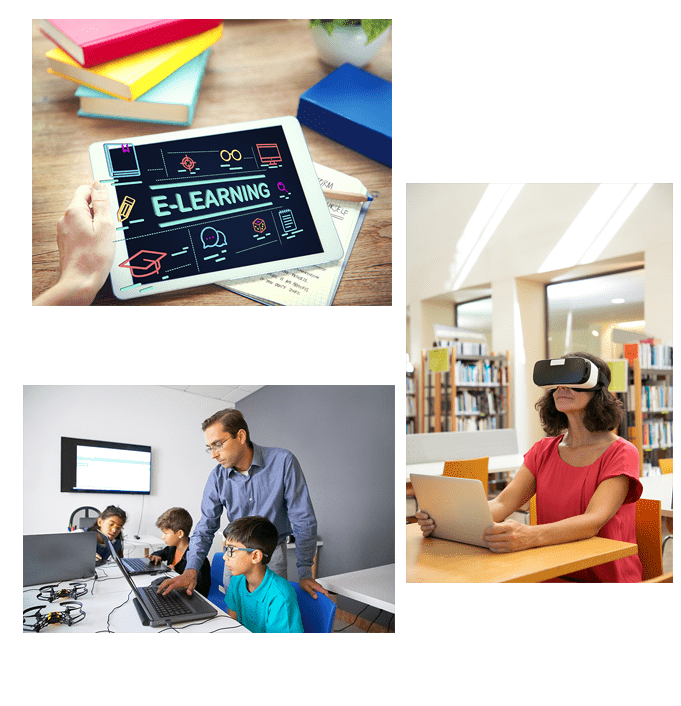


Grow with Our NextGen Solutions
We provide innovative solutions for achieving excellent results. With personalized learning pathways, advanced technology integration, and real-time progress tracking, we equip learners with the skills they need to thrive in today’s rapidly evolving world.
15+
Years
50+
Clients
25000+
Students
Product categories
Our tools empower a modern, efficient, and interactive educational ecosystem.

Learning Platform

Assessment Platform

Analysis Tools

Archive & Communication System
Providing Free Software Solutions to Upgrade Learning Experience and Productivity
We offer many tools designed to support organizations and learners across a range of functions. From advanced learning platforms to analysis tools, our software solutions are created to upgrade productivity and elevate the learning experience.
These tools create opportunities for people to learn, grow, and succeed in an increasingly digital world.
Developers can modify, improve, and adapt Techalone’s open source software solutions to meet specific needs.
Our goal is to support students, institutions, and businesses by offering affordable, user-friendly, and customized software solutions.

Our Products
Discover our products that align with your needs, and transform your business to new heights.

Learning Management Systems (LMS)
A comprehensive platform for creating, managing, and delivering online courses. It has features like course creation tools, student tracking, quizzes, assessments, and real-time feedback.

Assessment and Analytics Tools
Tools that allow educators to create and distribute tests, quizzes, and surveys. These can also analyze student performance, generate insights, and offer suggestions for targeted interventions.
Do you want to know more about our products?
If you have any enquiries regarding our products or services, please feel free to Contact Us